Understanding GNSS Antennas: The ultimate guide
Ramya Sriram
6 min read
28th May, 2024
S-GNSS

Global Navigation Satellite System (GNSS) antennas provide a critical interface between GNSS receivers and satellites, enabling precise PNT services as they capture GNSS satellite signals in multiple frequency bands. In this blog, we will discuss the different attributes and types of antennas and the effects they have on GNSS receivers’ ability to accurately measure the satellite signals.

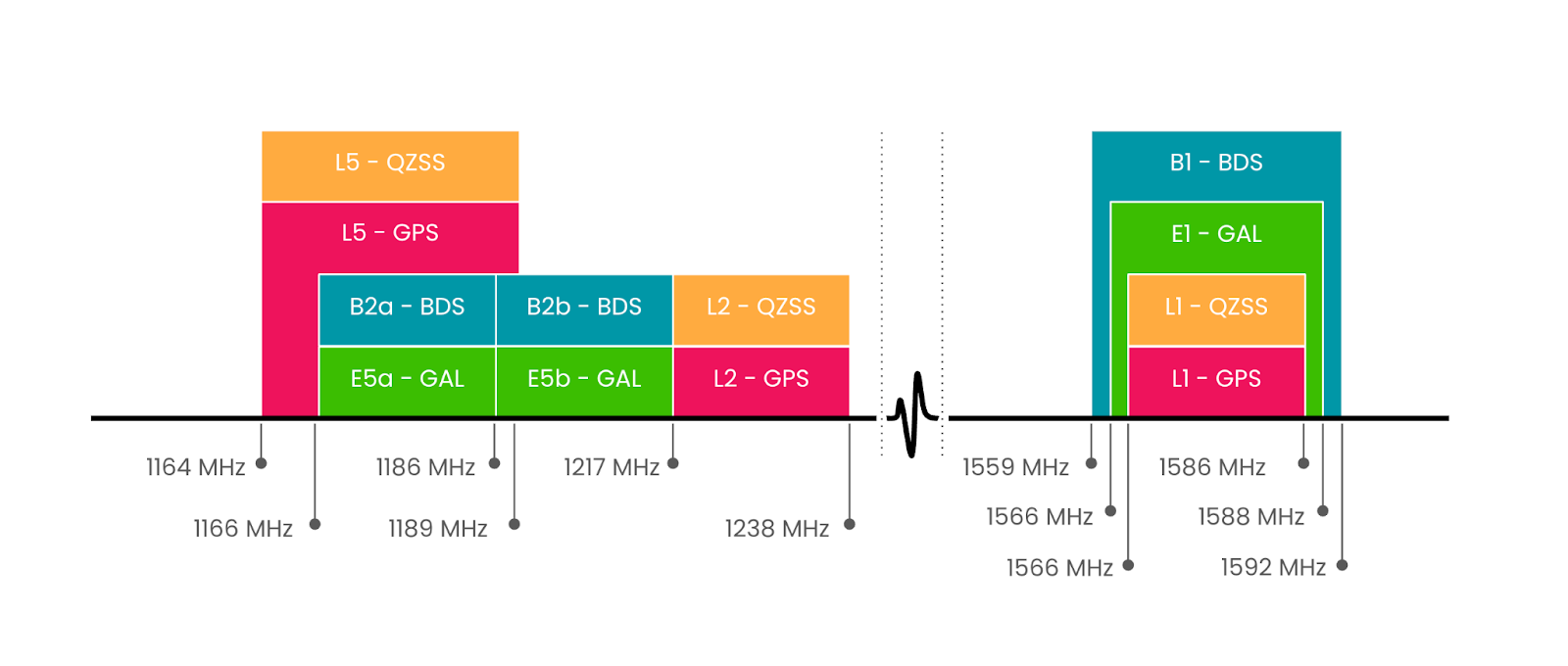
Figure 1. An overview of the GNSS frequency spectrum [1]
GNSS antennas: Key characteristics
The key characteristics of a GNSS antenna can be summarised as:
Filtering and Amplification: GNSS antennas can be passive or active, i.e. they encompass active elements such as built-in filters and low-noise amplifiers (LNAs) to mitigate unwanted EM and/or out-of-band interference and enhance signal quality (signal-to-noise-ratio), respectively.
Gain and Radiation Pattern: Antenna gain is a measure of how much the antenna can amplify the incoming signals, while the radiation pattern has to do with how the antenna can capture signals from a specific direction(s). A higher antenna gain improves signal quality (signal-to-noise ratio), especially in challenging environments such as urban canyons or under canopy. The radiation pattern is designed carefully to ensure that the antenna obtains signals only from desired directions and excludes (attenuates) signals from unwanted ones.
Polarisation: This relates to the shape of the radiated EM signals that the antenna can receive (and transmit), the most common types are:
Linear: when they oscillate on a plane, e.g. horizontal.
Circular: when the radio wave rotates about an axis. Depending on the rotating direction, these signals can be right-hand circularly polarised (RHCP) – when the electric field rotates clockwise as it comes towards us, or left-hand circularly polarised (LHCP) – when it rotates anti-clockwise.
Elliptical: when the signal propagates as an elliptical helix.
A combination of the above forms.
Multipath Rejection: GNSS antennas with multipath rejection capabilities (e.g. choke-ring antennas) can mitigate errors caused by signal reflections and multipath interference, rendering them popular in maritime and automotive applications.
Form factor: It relates to the physical space that the antenna occupies, which is a critical hardware design factor especially in embedded applications with limited space on printed circuit boards (PCB’s).
Robustness and Mounting: GNSS antennas are designed to withstand harsh environmental conditions such as extreme temperatures, moisture, and mechanical stress. They often feature ruggedised enclosures and weatherproofing to ensure reliable operation in outdoor applications. Another consideration is the mounting options which are suitable for a specific industry and application, e.g. base station, automotive, maritime etc.
GNSS Antenna Types
GNSS antennas come in a wide range of designs combining the characteristics discussed above. In all cases there are tradeoffs to balance these characteristics in order to optimise the hardware design, antenna performance and cost. The following antenna types are the most common ones which are being used in the GNSS industry:
Chip (loop) antennas: these are passive linearly polarised (so they capture half of the incoming signal) used in embedded applications and printed circuit boards (PCB’s).
Microstrip Antennas: these are linearly polarised, manufactured on PCB. They are small form factor and inexpensive, and used in embedded systems and small electronic devices, e.g. smartphones.
Patch Antennas: a very popular type of antenna in GNSS with, typically, right-hand circular polarisation (RHCP) and suitable for applications requiring moderate to high-gain. Patch antennas are lightweight and easy to install. They can be passive or active (i.e. encompassing low-noise amplifiers for better signal-to-noise ratio performance).
Dipole antennas: these comprise two conductive elements and capture linearly-polarised signals over a wide frequency bandwidth.
Helical Antennas: typically active (but may be passive too) antennas encompassing a coil around a central axis. They are RHCP and omnidirectional radiation which renders them suitable for many applications ranging ones where the antenna orientation may vary or base stations due to their high gain.
Multi-element Arrays: These consist of multiple antenna elements arranged in a specific configuration, e.g. hexagon (6-element), or 2×2 (4-element). They provide enhanced performance in terms of gain, beam-steering and nulling, and interference rejection, making them suitable for high-precision GNSS applications. They are expensive, typically employed in military or specialised civilian applications requiring advanced jamming and spoofing mitigation.
In summary, GNSS antennas play a critical role in enabling accurate positioning, navigation, and timing services by feeding the GNSS receiver front-end with good quality signals. Selecting the most suitable GNSS antenna is a multi-factor balanced decision as there are a lot of trade-offs depending on small form factor, mounting options, weight, radiation pattern characteristics, gain and cost.
How can FocalPoint help?
S-GNSS®, powered by our patented technology, Supercorrelation, can be applied to almost any GNSS receiver to dramatically improve antenna performance for Automotive, Smartphone and Wearable applications. An S-GNSS® receiver uses angle of arrival to reject multipath and undesirable noise, while boosting line-of-sight signal measurement. Using software only, S-GNSS® acts like an antenna upgrade, mitigating low cost or small form-factor antenna. Learn more about S-GNSS®
References


